|
HOME SERVICES CURRENT PROJECTS GALLERY ABOUT CONTACT |
Pictures and information about current, recently finished, and future projects.
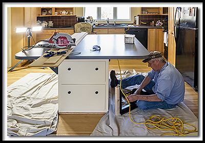
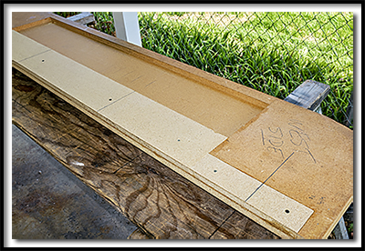
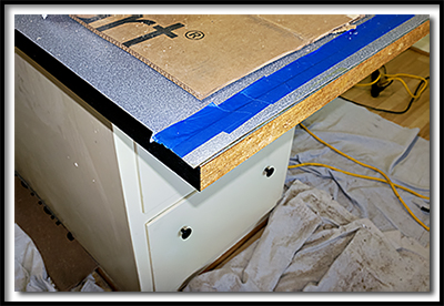
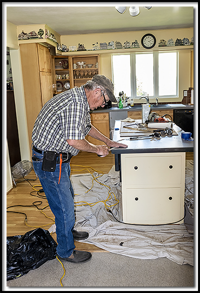
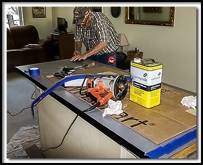
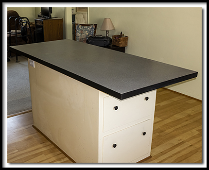
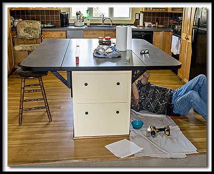
Recently one of them had to start using a walker. The space between the edge of the island top and the refrigerator made for tricky maneuvering with the walker. Several instances of falling toward the refrigerator had happened. The solution they came up with was to make fold-down sections on either side of the island. This would open up space for the walker, and also give them more room in the kitchen. They could still have a large island for guests by folding the sides up, and folded down, it was just right for meals for the two of them. They did not want to replace the island with a smaller one, they wanted to keep this one, and remodel it. In the above image, you see the custom straight edge, made for the circular saw, to get as perfectly a straight cut as possible. It worked very well. Mike is installing custom folding brackets, that will hold up the sides when cut with the saw.
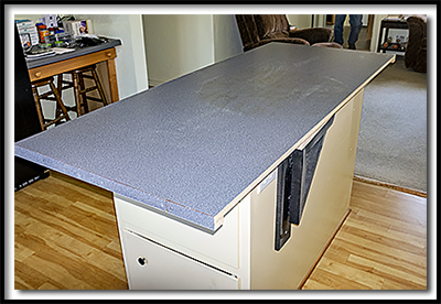
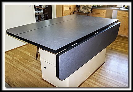
We did not have that luxury. We had to glue the laminate edge to the side of the top, and against the edge of the laminate on the top. Just backwards of normal. We used a router with a flush cut bit to trim the top of the laminate edging. Wrong choice. We had to use a scrap piece of laminate we had removed, lay it on top of the laminate top, and *then* use the flush cut bit with the router. Otherwise, because everything was not perfectly at a 90 degree angle, or perfectly flat, the flush cut bit removed some of the top laminate. Old tops do interesting things over the years....shrink....warp, you get the idea. What this means is that you get to finish the edge with a file. Very. Carefully. Our install of the edging was not perfect. But it was very, very close.
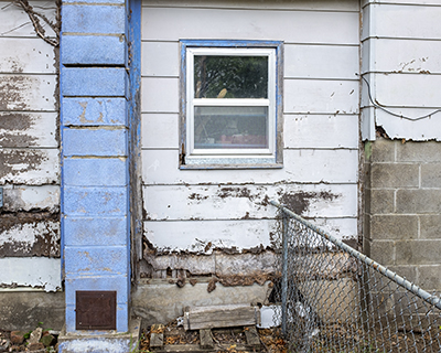
HOUSE CORNER REPAIR While waiting for better weather to continue on the Garage job, a customer called and needed some grab bars installed. Installed 3 grab bars, and a circular hand towel holder in two bathrooms.
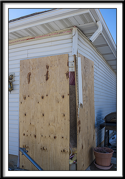
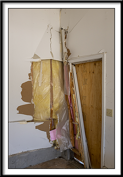
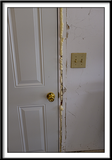
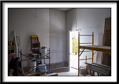
Walk door was destroyed, and wall framing disturbed.
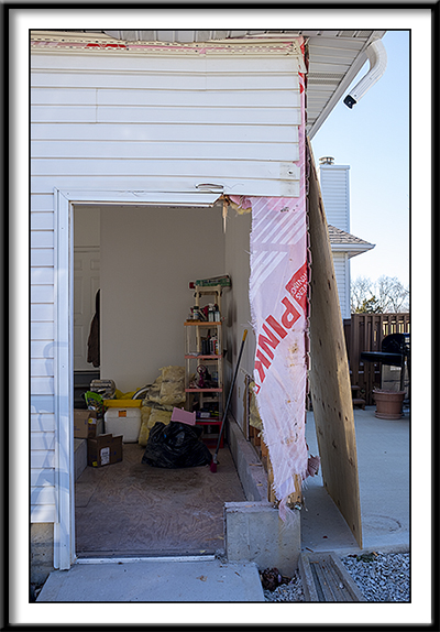
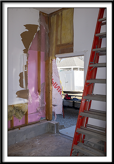
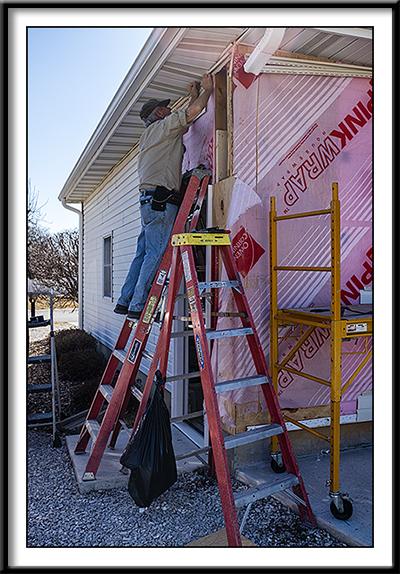
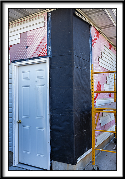
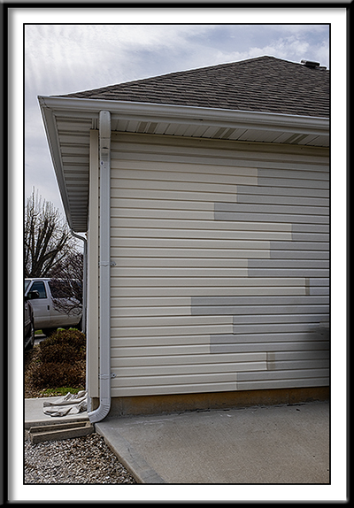
We will remove siding from a back wall of the house, to replace damaged siding on east wall of home, so that from the street, that siding will be the same color as originally installed when home was built. We will use the customer approved vinyl siding to replace the original siding removed from the back wall of the house. Not a perfect solution, but one the homeowner thought would be alright. The back wall is not viewable from any street. (Alternative was to re-side a lot of the house.)
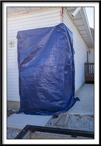
This project is finished.
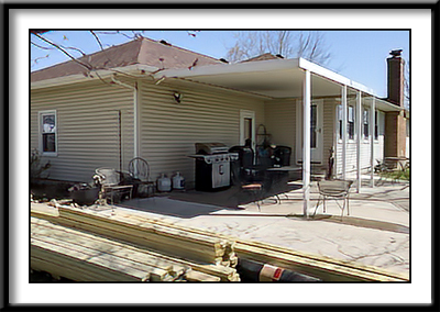
Customer needed handicap ramp built. Originally planned for inside the two-car garage, for easy access to vehicle for transport for doctor visits, etc. However, after planning ramp, the slope of the ramp built would be too steep for motorized wheelchair (electric scooter). After further consideration, customer decided to build ramp out the back door, from the office/living room area, and onto covered concrete patio.
This would allow for ADA maximum suggested slope angle of 1 inch rise for every foot of length for the ramp. A five foot landing area at the end of the ramp, would lead to a concrete sidewalk that went around the garage, so that vehicle access would be optimal. ADA suggests that 1 inch rise for every 16 inches of ramp length, or 1 inch rise for every 20 inches of ramp length would be even better. We only had room for the 1/12.
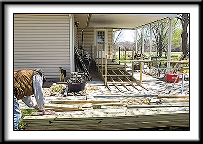
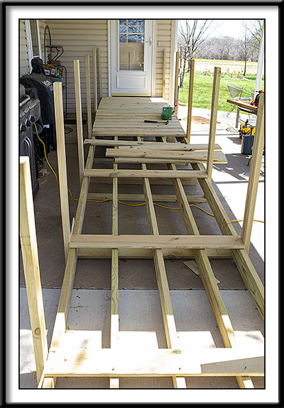
Five stringers using 2x6 treated yellow pine, 12 inches on center, with maximum length of 8 ft between support, makes for a serious floor system. All deck boards were fastened with two screws at each junction of the 5 stringers. Total rise at the house steps is about 18 inches. The ramp is 18 foot in length, and an additional 12 inches of non-slip solid rubber transition ramp threshold, extending total ramp to 19 ft.
This makes for a very comfortable walking rise, and the treated floor has excellent traction.
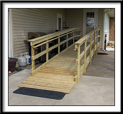
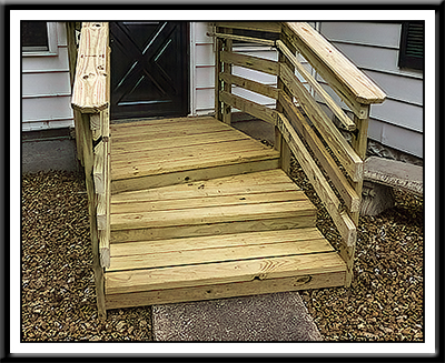
Here you can see the finished ramp. A secondary hand rail placed for convience of walkers and for wheelchair occupant, and a barrier rail on each side of the floor prevents accidental travel off the sides of the ramp.
Not one single nail was used in this project. All posts were bolted to outside stringers with galvanized bolts. For everything else, we used GRK R4 screws, of varying lengths, which are ESR-3201 approved for structural applications, including using treated wood. These are available at Full Line Lumber here in Clinton.
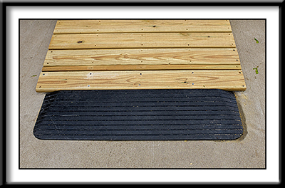
For the maximum amount of safety and smooth access to the ramp, we used Silver Spring's solid rubber threshold ramp. Click below to see it at Amazon: Silver Spring threshold at Amazon
The stringers were cut on angle, in such a way, that where the stringer ends, with a decking board laid on top, it would be 1-1/2 inches thick. Since there was not enough wood below the last two deck boards to fasten with screws, we used special concrete fasteners to screw the deck boards and the stringer end to the concrete patio below. The 1-1/2 inch rubber threshold ramp then matched the thickness of the stringer/deck board, and then sloped down to almost nothing, extending the ramp length, and making for a super smooth transition.
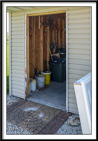
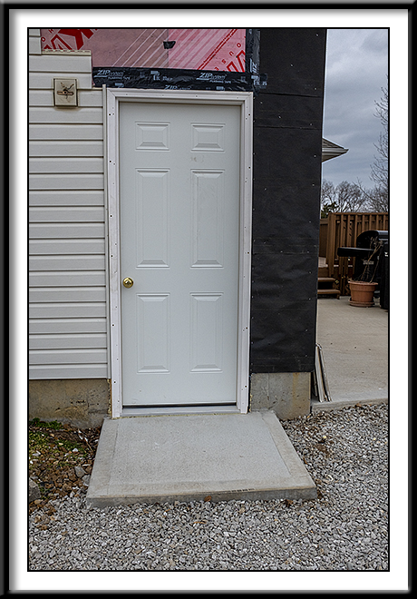
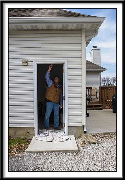
Customer wanted his un-attached garage walk door replaced. Garage was built 12 years ago, and every rain, water leaked through the door opening into the garage. The door sill on either side had started to rot, and he was tired of the water problem. He purchased a new door and a storm door for this project at Lowe's in Warrensburg. He told us he had to go through 5-6 door units to find one that was put together right or not damaged.
We have removed the old door unit in this picture, cleaned the sides of the door opening, and the concrete where door sill will be set. The original installation used silicone caulk to seal the door sill to the concrete, and this is where major part of the water leak problem was. Silicone is worthless to seal a door sill to any material. I quit using silicone years ago, when I saw how poorly it lasted as a sealant. There are probably applications where silicone works fine. Probably.
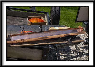
Manufacturer's today require a "pan" to be used under all exterior windows and doors. A pan will allow water or condensation that occurs under the window or door, to drain to the exterior of the wall, keeping it away from vulnerable material. Want to know more about window and door pans? Click here to visit website of a popular brand of window/door pan. While PVC would probably be a pretty good choice for a door pan on concrete, aluminum would not. I thought an even better choice would be copper. I know, it is expensive, to say the least! However, copper flashing is normally considered to last "as long as the structure it is applied to". It also does not react to the chemicals in concrete. It has been used as the top choice for exterior flashing for a long, long, time.
So, I put the metal brake in the trailer, with a box of 16 ga. copper, and formed a pan at the job site.
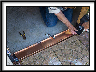
Here you see the copper pan installed on the concrete floor. What you don't see is the Polyurethane Sealant we "troweled" on under the pan, and up the sides of the door rough opening studs on either side. Also, I have to admit to a mistake here. I mistakenly made the pan too narrow. I wanted to have the front lip of the pan to go down over the front of the concrete edge, to allow moisture to drain down the edge of the slab. That worked out OK. However, I misjudged the depth of the pan. The original door installation was wrong from the beginning. What I mean is that the front section of the original aluminum door sill was never supported by anything! If you look at the first picture in this series, yoou will see what I mean. There is no concrete protrusion at the door sill area, to rest the door sill on. The customer told me that he just put the stepping stones under the sill that stuck out, and figured that was good. Well, maybe it would be if it never rained, oh well. Worse, the ground under the stepping stone did what dirt does...it fell/shrank down below the door sill enough that when you stepped on the sill to enter the garage, the aluminum sill would bend quite a bit. He told me he just avoided stepping on it, because he did not use the door much. So I just made the pan fit from the front concrete edge, to the back edge of the interior wall. My mistake was that since there was no sheetrock or trim on the garage wall interior, when we set the door unit into the opening, the door unit required another 1/2 inch of pan depth to accomodate the 4-9/16 jamb width of the door unit. I have to say here, that I work with a carpenter that is in the engineer class of carpenters. I said, now what? He said, just cut the back lip off the pan, and make an extension to fit the door jamb width. So we did. Sealed it with more polyurethane sealant, and it fit perfect. Thanks, Mike. When you use a pan, it is important that you seal the back lip, so that the door sill seals against it to prevent air intrusion, and to direct the moisture back to the front for drainage. You do not seal the door sill to the pan, except for some sealant at a 90 degree angle to the back lip. Click below for more information on installing and sealing a window or door pan:
Installing and sealing a window or door pan.
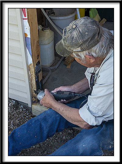
Once we had the "adjustable door pan" in place, and set the door unit in the opening, we noticed that the door unit did not fit the opening at the bottom. The customer alertly mentioned that he thought the wafer board sheathing used had absorbed enough water to swell quite a bit on each side at the bottom of opening. He was right. The house wrap used on the exterior of the wafer board sheathing did not keep the water that was traveling between the bottom of the door sill and the concrete floor. It just acted as a sponge and sucked the water up, swelling and increasing the thickness considerably. In this picture "Engineer" Mike uses an oscillating saw to remove material from the wafer board to get it close to original thickness. We used flashing tape over the repaired waferboard for weather protection, restoring the integrity of the house wrap.
One further improvement we made was to use tapcons to install a 2x4 support under the door unit sill. We used a table saw to "cut out" a recess in the top back of the 2x4, that matched the front copper flashing lip, so that drainage for the pan would not be impacted. The cut out directs water to either side of the door unit, and further impedes ground water from entering the pan. Sorry, I didn't get pictures of that. You can just see part of the treated 2x4 support in this picture, and the entire treated support in picture below.
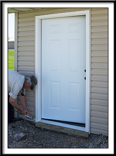
Finally, caulking between the brick mold on the door unit and the j-trim for the vinyl siding completed our part in this door replacement. Our customer was extremely helpful, installing the lockset and the storm door for another finished project.
Everything went just exactly as the below video describes. (I still have my Panasonic drill just like the guy in the video is using! lol ) Click here to see Andersen video. Well, everything went "almost" like the video. Exception for this window was that the top jamb cover's front edge was formed to fit into a "kerf" in the window frame, and was held in place by the window trim. The trim had to be pryed out enough for the jamb cover's edge to move a little so the top jamb cover could be removed. Not a big deal, but could have been is cover was forced without moving the trim out a little. Removed left side bottom half of jamb cover without hurting it, just as in previous window sash balance replacements. We did have a new bottom half jamb cover just in case, as suggested by Andersen. Customer has Andersen Narrowline Series 200 Double-Hung wood windows in their home. Manufacture date on this one is May 1988.That makes this window 34 years old, and it still looks great. Some years back I replaced sash balances in two other windows in this home, as well as an operator in an Andersen casement window. Windows are from 1987-1988. Everything worked out fine. One great feature of Andersen products is that the replacement parts fit perfectly, and restores the product to like new operating condition. Most of today's vinyl windows are throw-a-ways. You even see ads that tell you that if your windows are over 5 years old, it is time to get new ones! You get what you pay for. Contact Scott at Full Line Lumber in Clinton, Missouri for your Andersen Products and Parts.
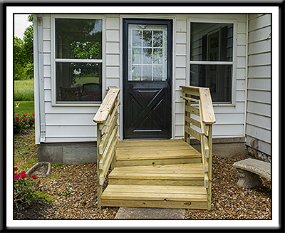
I need better access to my Sunroom, what do you recommend? 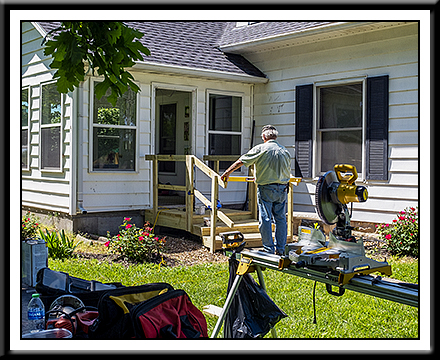
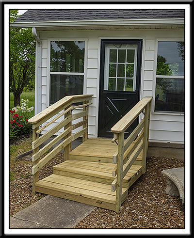
Steps leading into Sunroom were uncomfortable to use. No handrail was originally installed to use. Friends that would visit were at risk for injury, and customer wanted to change that possibility. We suggested building a wooden stoop, with shallower steps, much deeper than present steps, with sturdy handrails. Storm door finish had faded, and started to rust a little at the bottom. Decision was made to re-paint the storm door during the stoop construction. SUNROOM SOLUTIONS APPROVED BY CUSTOMER:
1. Build a wooden stoop.
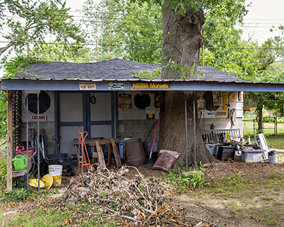
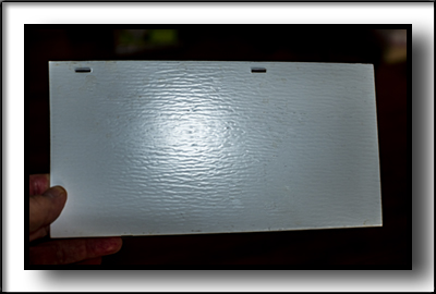
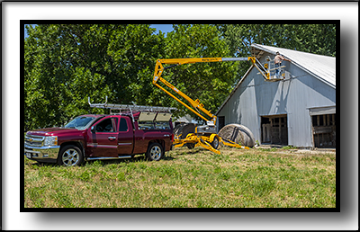
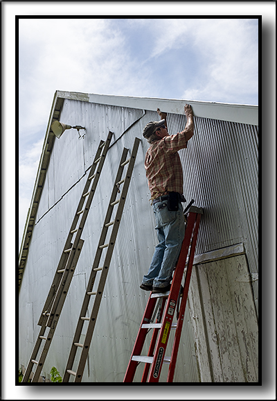
ADDITIONAL PROJECTS FOR THIS CUSTOMER: Customer had 20+ year old refrigerator that had handles that were deteriorating, and needed replaced, as cleaning them was not satisfactory. (We took care of this by ordering factory original handles, installed them, and this made a big improvement!) This refrigerator was a General Electric, and here is where we found the handles. Even though is an old model, replacement parts and pieces are still available! Fast service, and was an exact replacement! Click here for refrigerator parts. Customer had several outbuildings and barn on the property and wanted metal fascia cover installed on fascia trim. Normally, aluminum fascia trim is installed to cover the fascia trim on homes. The top edge of the aluminum fascia trim is pushed up under the roofing metal drip edge, and the aluminum fascia trim is then nailed at the bottom edge of the home's fascia board. The roofing drip edge allows the water to run off of the roof, and into the gutter, or yard if no gutter, without running down the fascia. Older Barns and other Outbuildings that have metal roofing do not have a "Roof Edge" installed. Any metal covering over old wood fascia does not have anything to be fitted to, so that rain will run off, and protect the wood fascia underneath. What we used on this project was custom made "finish trim", that the custom width aluminum fascia cover could slide into, and also lock at the same time. So we installed this custom 2-piece fascia on all outbuildings. Below are pictures of what we designed and used. We made almost 1000 lineal feet of trim for this project. About 500 feet of finish trim, and 500 feet of fascia panel. It took six rolls of textured aluminum trim coil to do the job. East roll is 50 foot long, and 24 inches wide.
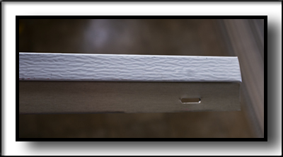
Above image shows custom finish trim that top of fascia panel will install. Elongated nail slot allows for expansion and contraction. This piece is two inches in height, and we make it in 10 foot lengths. Each building we worked on requires a different size finish trim and fascia trim, as nothing was "standard", to say the least.
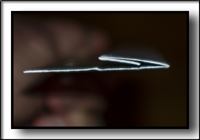
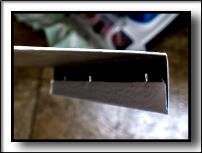
Above image shows end view of custom finish trim. It is bent in such a way, that when the fascia panel slides into the finish trim, the "snap lock" at the top of fascia panel, locks the fascia panel into the finish trim. We adapted some vinyl siding tools to accomplish much of the custom features of trims.
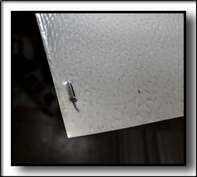
Above image shows "snap lock" at the top of the fascia panel in greater detail. This is what holds the fascia panel inside the finish trim. It slides from side to side, but is difficult to pull out.
Above image shows a section of the fascia panel. This particular one is 5-5/8 inches in width, and is made in 10 foot lengths.
Above image shows the bottom of the fascia panel. I made a "hem", and pre-punched holes for easy nailing. The holes are a larger diameter than the nails allowing for expansion. We used stainless steel nails.( Holes were punched about every 24 inches.)
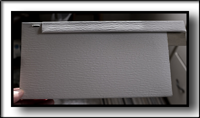
Image above shows how the fascia panel inserts into the finish trim, for a "finished look".
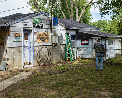
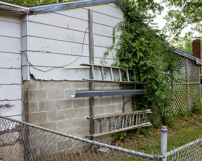
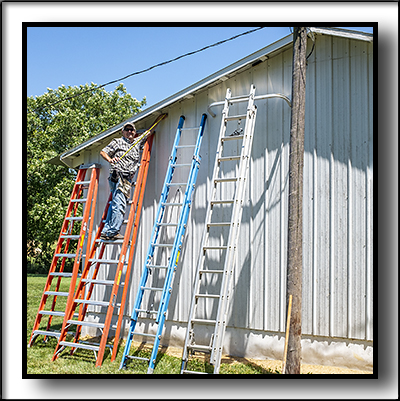
Some of the ladders we used...you can just step from one to the other. (Not a recommendation...)
And...when ladders just don't do it.
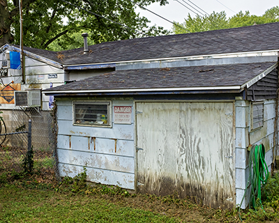
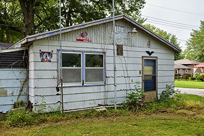
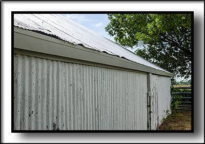
Fascia panels did improve the look of these old buildings...and eliminated future expensive paint jobs!
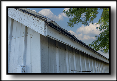
These are the fascia boards we had to deal with.
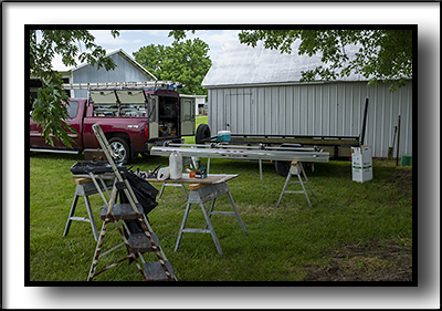
The job setup.
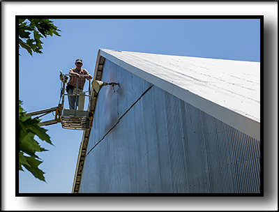
Master Trim Technician at work.
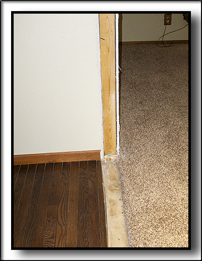
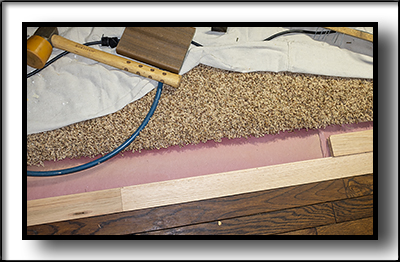
Finito. SHORT WALL REMOVAL AND REPAIR Customer wanted a short wall that divided living room from the rest of the home removed. The short wall was bordered by carpet on one side, and oak flooring on the other. When the short wall was removed, oak flooring needed to be pieced in where the short wall was, and the sheetrock wall patched where the short wall was fastened, and wall texture matched ready to paint. The header above also needed sheetrock to be patched and textured ready to paint. I should have took more pictures, sorry.
Image above shows where the short wall has been removed, exposing the floor and wall that needs repaired.
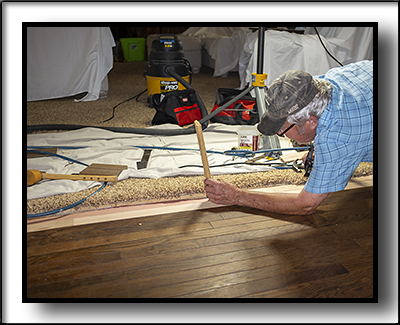
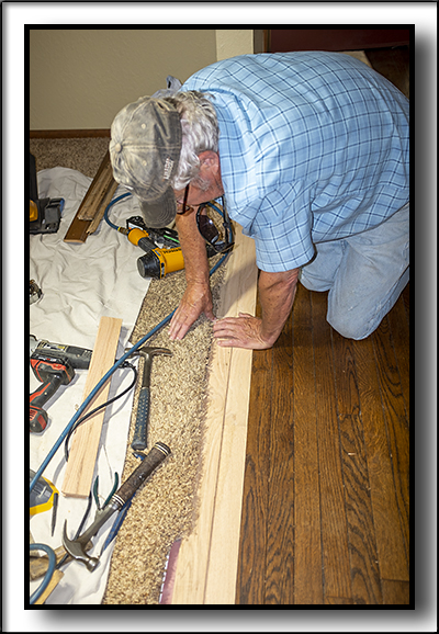
Image above shows Master Floor Technician preparing old floor for new oak flooring.
Image above shows new oak flooring being installed.
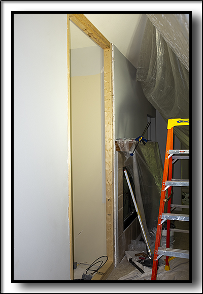
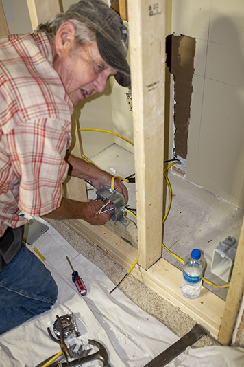
Image above shows Master Floor Technician finishing adding new flooring. We repaired all sheet rock on wall and header above, matched wall texture, so customer could repaint. It came out looking very nice. Customer had Hobson's come in and stretch old carpet to new flooring. Customer also had a professional floor refinisher come in and sand entire oak floor, restain, and re-coat floor...it looked absolutely fantastic! WALL JOB AND MORE Customer wanted a recess in living room wall used for armoire with television closed off, making the recessed area the same as wall all around it. We roughed-in a few studs, installed sheetrock even with sheetrock wall around, finished the sheetrock, textured it to match the rest of the wall texture, ready for paint. Cable access wiring needed installed in new section of wall, as well as two electric outlets. The recessed opening was right next to a fireplace, adding to the difficulty of finishing/texturing the new sheetrock to the old sheetrock wall surrounding the recessed opening. Adding interest to the project, the existing electrical wiring at the back of the recessed area, used for two electrical outlets, was not long enough to extend out to the new sheetrock. Basement was finished, and deterred installing new wiring long enough for new electrical outlets. Decision was made to use junction box to add extra wiring for outlets, inside the recessed area, and make access to junction box through a fake air vent. Problem solved. Customer had a new hardwood floor installed when we completed the wall remodel. Customer wanted two new floor outlets installed, so that electrical cords could be plugged into new outlets under furniture, to avoid cords running across the floor to the wall outlets. Here is a few pictures from that project:
Above image shows the size of the recessed opening in wall.
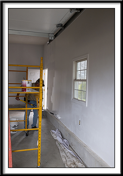
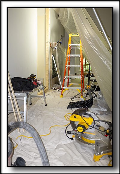
Above image shows we attempted to minimize dust when working on closing the opening.
In above image, Mike is working on extending cable and electrical for new outlets.
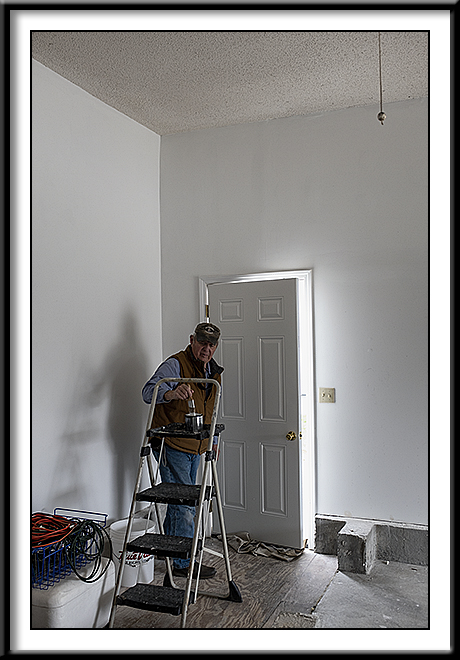
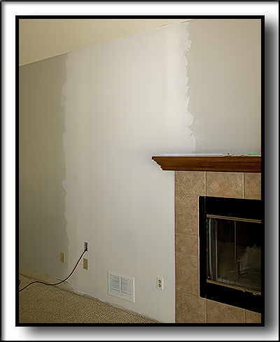
In the above image, new wall is finished, textured, and primed, ready for paint.
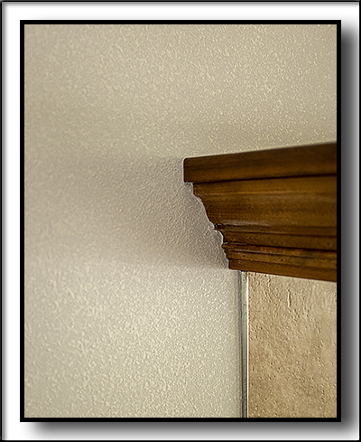
In image above, tricky sheetrock finishing and wall texture shown next to fireplace and mantle.
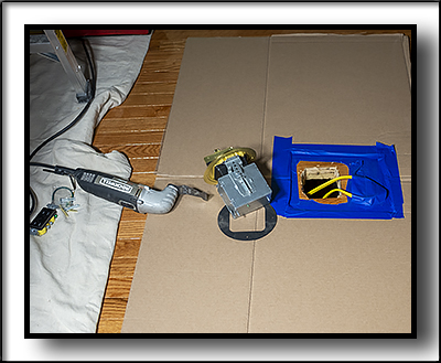
Shown in the image above is our effort to not mar the brand new hardwood floor, when we cut holes in it to install floor outlets.
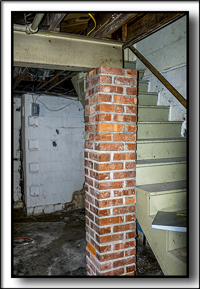
Image above shows new floor outlet. We installed two of them. 1932 HOUSE REPAIRS Customer needed several repairs on home. 1. Replace failing brick column in basement that supports main I-beam for house. 2. Repair spalled concrete block basement wall. 3. Repair/adjust basement window so that it will close to keep out air and rodents. 4. Install door head bolt to upstairs patio door. 5. Install deadbolts to main floor patio door and to back door. 6. Weatherstrip and repair back door storm door. 7. Replace shattered door glass on patio storm door. 8. Refurbish/clean oven exhaust fan. 9. Remove old sealant around kitchen sink, and replace with new sealant. 10. Adjust/repair spring bronze weatherstrip on 3 exterior doors. 11. Seal cracks on and around front concrete stoop.
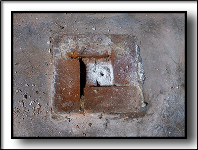
Above image shows a brick column that supports main steel support beam for the home. It has started to buckle.
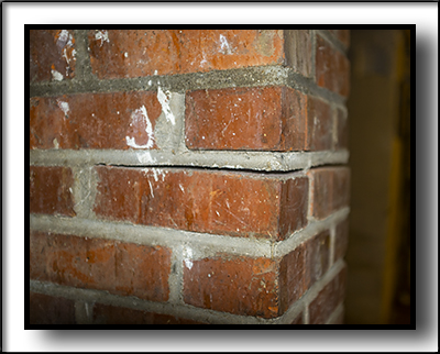
Image above shows the cracking where the brick column has started to buckle.
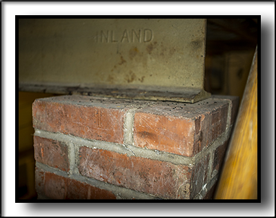
Above image shows main steel beam for home sitting on top of brick column. The 90 year old column is filled with bricks and mortar inside.
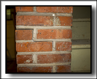
Image above shows the other side of the brick column.
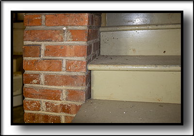
Image above shows the cause of the buckling column. Wooden stairs lead to first floor of home. To the right, there is a concrete wall. This wall is buckling just enough to push a stair tread against the brick column, causing the brick column to buckle. The stairs were build tight against the concrete block wall to the right, and the brick column was almost touching the stair tread to begin with. It did not take much deflection of the concrete wall to cause the problem.
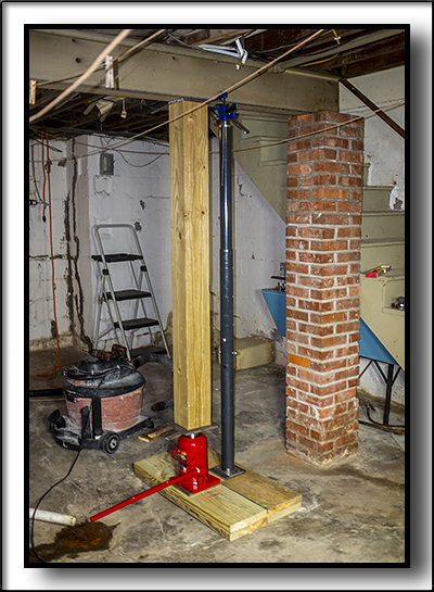
Image above shows the main beam being jacked up enough to take the load off of the brick column. We were careful to not go up more than 1/8 of an inch, to avoid cracking and shifting of plaster walls in the house. We used a 50 ton hydraulic jack, with 6x6 treated timber, with steel plates top and bottom to prevent imbedding the jack top into the wood. We used double 2x10 treated yellow pine, 36 inches in length, to spread the load under the jack. There was a slight dip in the concrete floor under all this, and when we jacked up the beam, the wood completely deformed to match the dip in the concrete floor. Prior to lifting the steel beam, I made a "story-stick", the exact height that measured the bottom of the beam to the concrete floor. I used two 1x2's, and slid them together until they were exactly the distance from bottom of beam to the floor. I then screwed them together. The "story-stick" would be used to take to the welding fabricator, for an exact measure, for length of new support post, and also to use when we re-loaded the beam on the new permanent steel post. You can't take a chance on steel tapes, as you have to "guess" at the measurement where it bends at the measuring point. After 90 years, the steel I-beam main support was dead on level, so we wanted to return it to the same identical position it was after we lifted it. Success is in the details. It is estimated the total weight of this 90 year old home is 250,000 pounds. Of course, where we were jacking the beam was not this heavy...but still, it was a LOT of weight, and we noticed it as we lifted the beam. Homeowner hired a structual engineer to make suggestions about how to go about this part of the project. He recommended the size/type of the new steel column, as well as the temporary column you see to the right of the wood beam. His findings were noted on the building permit. The hydraulic jack alone could not be depended on to keep the steel beam where we stopped. Hydraulic jacks "creep" under a load over time. The temporary steel column to the right was adjusted with the "screw" adjustment to just the right height, to assure us that the steel main beam would remain at the right height while we demolished the brick column, and installed the new, permanent steel column. Here is a link to the temporary post we used: Click here to go to temporary post information
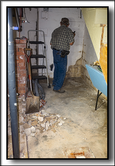
Image above shows the brick column demolished. We stacked the bricks up for the homeowner, and suggested they keep these bricks for use when needed. They are bricks from the same period as the rest of the home. The home has a brick veneer, and some brick "fence", so these bricks will be invaluable for future use. The brick column was extremely easy to demolish. 90 year old lime mortar is nothing like today's modern mortar, even though it served it's purpose well. Above image shows temporary column in place. We left the hydraulic jack in place.
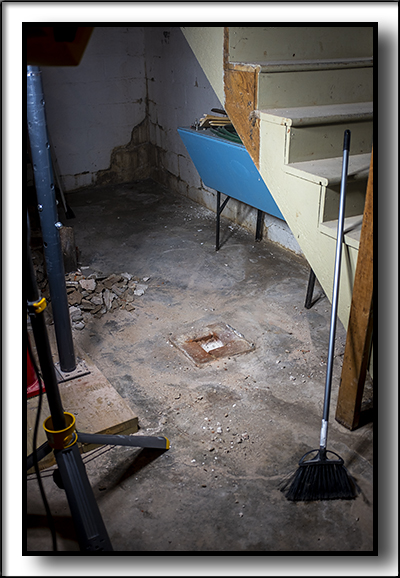
Image above shows brick column demolished and area cleaned up.
We moved the jack setup and temporary post back a few feet, thinking we might have to excavate and pour a new footing for the new permanent post
Above image shows residue of concrete footer underneath last row of bricks that set below the level of the concrete floor. We drilled down 12 inches plus to check the depth of footing below. We made the decision to go ahead and set the new permanent support post on the same footing the brick column had stood for 90 years, and had supported a perfectly level main beam.
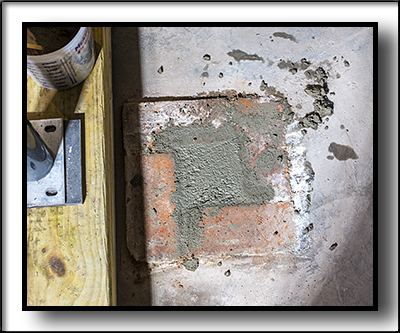
The last row of bricks, that are level with the concrete floor, were surrounded with concrete. We filled the space in the middle of the bricks with 4000 psi strength concrete, to make for a solid base for new support post.
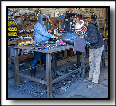
Image above shows Shawn Custer's crew assembling the new permanent support post. Engineer had specified schedule 40, 4 inch o.d. pipe. I had them weld a 12 inch x 12 inch 3/4 inch thick plate steel to the bottom of the post. This would completely cover the last row of bricks, and give similar support from the footer that was below the floor. I also had them weld a 4 inch x 6 inch 1/2 thick plate steel, to bolt to the house main I-beam. I highly recommend Custer's Welding and Fabrication here in Clinton.
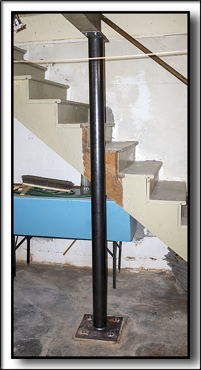
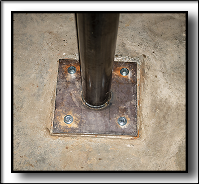
Image above shows the new permanent support post in place.
Image above shows the 3/4 inch steel plate post bottom. We used 6 inch long and 1/2 inch diameter masonry bolts to fasten it down.
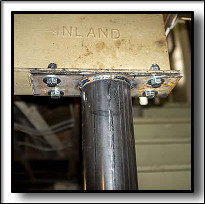
Image above shows the 1/2 inch steel plate post top, bolted to the mail steel I-beam.
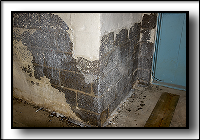
Image above shows spalled surface of concrete block basement wall. 90 years of water on exterior of wall, allowing some moisture to penetrate the blocks have taken it's toll.
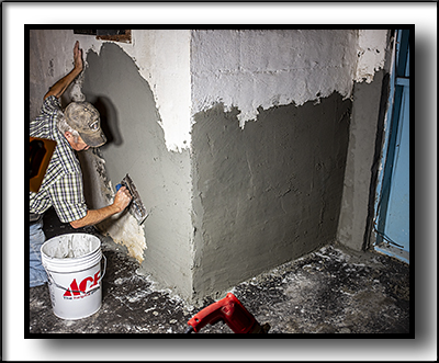
Above image shows our highly trained technician applying type-N mortar to the basement wall. The damaged area was scraped, then wire brushed and vaccumed to remove all loose particles possible. Felt paper was laid down at the bottom of wall section to be repaired, and acrylic bonding agent was applied to the damaged areas to be covered. The next day, the surface was rubbed down with a rub brick to smooth surface.
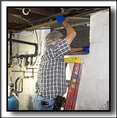
Image above shows our Master Window Repair Technician cleaning and diagnosing a basement window that would not close, and allowed air and rodents to enter.
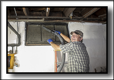
Above image shows window being cleaned after adjustments were made to allow window to close.
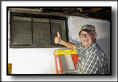
Image above shows a succesful solution to closing and sealing the basement window.
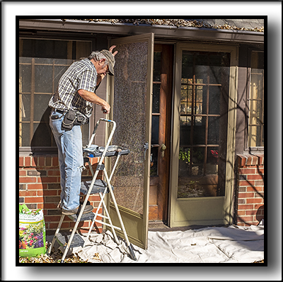
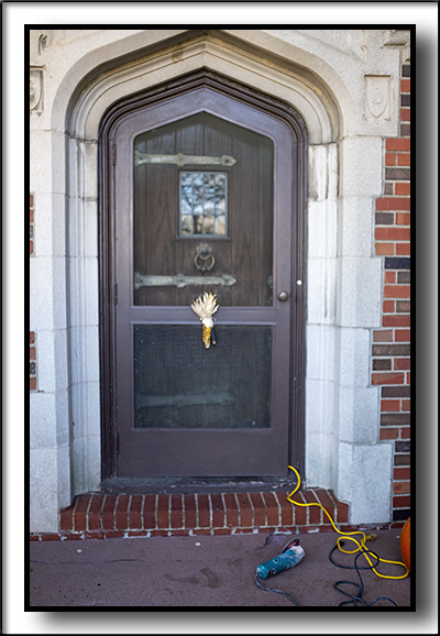
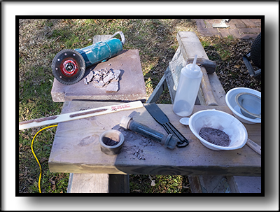
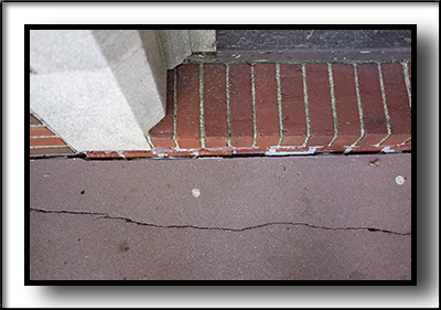
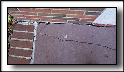
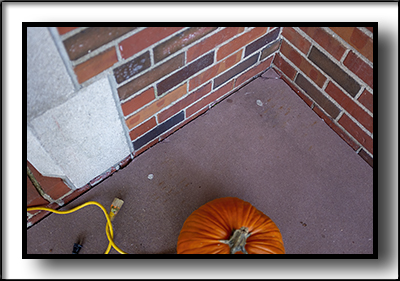
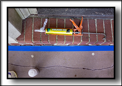
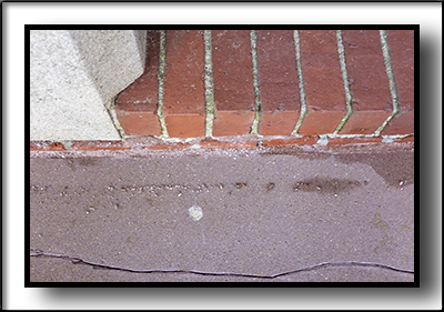
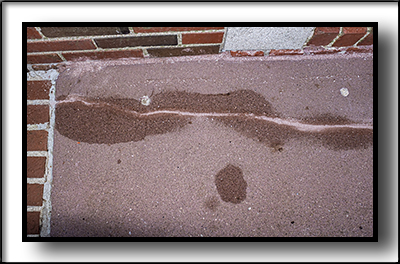
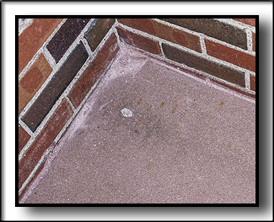
Image above shows customer's French Storm Door, with one panel broken. This is why tempered glass should always be used in doors. It cracks, pretty much stays together, and does not have sharp dangerous shards of glass that can cause serious damage to people. We took the glass out, and had new glass put in the frame, and replaced the frame in the storm door. 1932 HOUSE REPAIRS-FRONT ENTRANCE STOOP CRACK SEALING Front entrance concrete stoop had large gaps between concrete and the house brick veneer, allowing water to run down the exterior of the basement wall below. Concrete also had some minor cracking in the slab. We put foam backer board about 1/2 inch below surface of concrete where it met the house wall, so we could fill the crack with Vulcan 116 Polyurethane sealant. After power washing the stoop, and a section of the adjoining sidewalk, we discovered that the concrete stoop was a reddish color. Over the years, mildew and dirt had disguised this color. After searching online and locally, I finally found a color of Vulcan 116 Polyurethane sealant that came close to matching the original reddish tinted concrete. I ordered the sealant locally from Full Line Lumber here in Clinton. I realized that just the sealant alone would not look close enough to the old concrete, so decided to put some "sandy texture" on top of the sealant. I found a patio block at Westlake Hardware here in Clinton, that was pretty close to the reddish concrete color. I cut small strips of the patio block with my small grinder and diamond blade, and smashed them up with a small sledge, into sand size particles. Using blue painter's tape along the edge of the cracks, applying the sealant, spraying a mist of 409 All Purpose Cleaner on sealant, so that when I smoothed it with my finger, it formed a perfect bead. I then poured the patio block "sand particles" to the sealant, for a pretty good looking sealant application. Not a perfect match, but pretty good. My customer liked it, and that is what matters. (The white spots you see are where termite guy drilled holes in concrete, and the wet spots are where the 409 cleaner has not dried.) Images below tell the story:
1932 HOUSE REPAIRS-MISCELLANEOUS
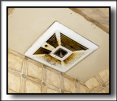
Image above shows condition of kitchen range exhaust. Mike removed the entire range exhaust, and completely cleaned cover, motor, and housing. It absolutely looked like a brand new one. Re-installed and worked like a champ. We looked for a new one to replace this one, and because of the unique framing, could not find one to fit.
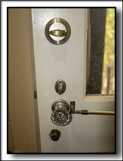
Image above shows a deadbolt installed in the back door. Another identical deadbolt was installed in a front patio door. Mike also installed a head bolt in an upstairs patio french door. Sorry, no pictures. All exterior doors in this home have Bronze Spring weatherstripping. If you do not know what that is, click on this link below to see information about it: Click here for Spring Bronze Weatherstripping information When a new strike plate is installed in a door weatherstrip system, that uses Spring Bronze Weatherstripping, a small section of the Spring Bronze needs to be cut out. To give that section of the door effective weatherstripping, you need to install a Spring Bronze Lock Strip, to bridge the section of weatherstripping you cut out for the new lock. I ordered Spring Bronze Lock Strips from Kilian Hardware and installed the lock strips on both door jambs that had new deadbolts installed. The main entrance door to the home had a lock strip installed, but it was deformed, and I was able to rescue it, and restored it to original shape. Spring Bronze Weatherstrip systems are estimated to last 100 years...so all of them in this house should be good for another 10 years! lol Customer needed a re-caulk around edge of kitchen sink. I removed the old caulk, with utility knife, sharp putty knife, and scraper blade on oscillating tool. Cleaned the surface with lacquer thinner. Bartender's Friend will remove any staining or marks you need gone. Used a job LED bright light to make sure all caulk was gone. Used blue painter's tape all around the perimeter of sink, so that tape was on both sides of where I wanted the caulk to be applied. I like Lexel brand caulk for sinks, it is chemical resistant. It will even stick to damp surfaces, just in case there is a little moisture left on sink edge. I use my finger to smooth the caulk bead, and as soon as possible remove the tape carefully. You can use water, alcohol, 409 cleaner, etc. to wet your finger so that no caulk sticks to your finger and messes up your application. Sorry, no pictures of this task. FUTURE PROJECTS COMING SOON...
1. Customer needs a bathroom door repaired/re-installed.
2. Customer needs some aluminum trim coil formed for exterior window trim.
3. Say, Carroll, while you and Mike are here, would you mind....
|